I put the surface calibration sample in the big sample holder and I found the position of the sample surface along the Z axis is about 8mm different with respect to the little reference sample holder. This just means the scan should start from Z0=12mm instead of Z0=20mm.
I put the sample of LMA in the holder and I attached the holder to the translation stage, I acquired 1hour of noise and it turns out to be 18microV std with no spiky noise. This is means the presence of the sample holder doesn't increase the noise.
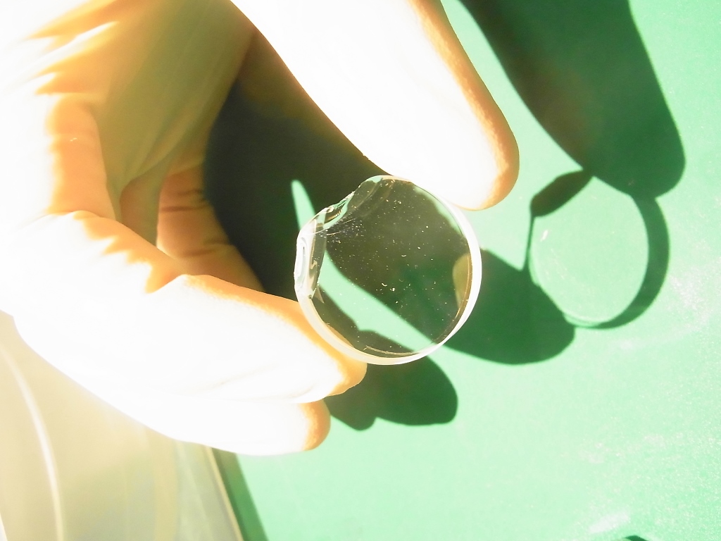
I acquired the scan of the coated sample they gave me at LMA (sample 15033, they measured abs=12.8ppm @1064). Pump power = 171mW (LD current = 1.2A)
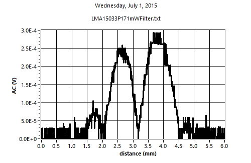
The first image shows the scan along Z axis of the sample. We can see two peaks and this is not the coating absorption patter we see in the calibration. The reason is that we are looking at the surface which doesn't have a HR coating
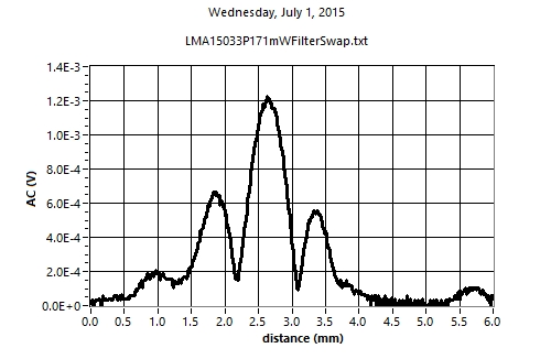
The second image shows the scan along Z axis of the flipped sample, in order to see the right HR coated surface. It has a pattern very similar to the calibration scan, a high peak at the surface and the two smaller peaks of diffraction effects.
The absorption calculated from this measurements and the calibration factor with the reference sample we have (surf_abs = 22%) gives 107ppm, almost a factor of 8 higher than the nominal value (12.8ppm). We are understanding the meaning of this. We will check the calibration factor, how the software filtering works and how clean is the surface of the sample.
The formula is Abs=AC/(DC*Power*R) where R is the calibration factor, it has a value of 10+/-1 and it is calculated with the surface reference sample calibration (abs=22%).