LEDs of OSEMs should be screened by measuring their intensity noise beforehand, so a setup for this business is prepared.
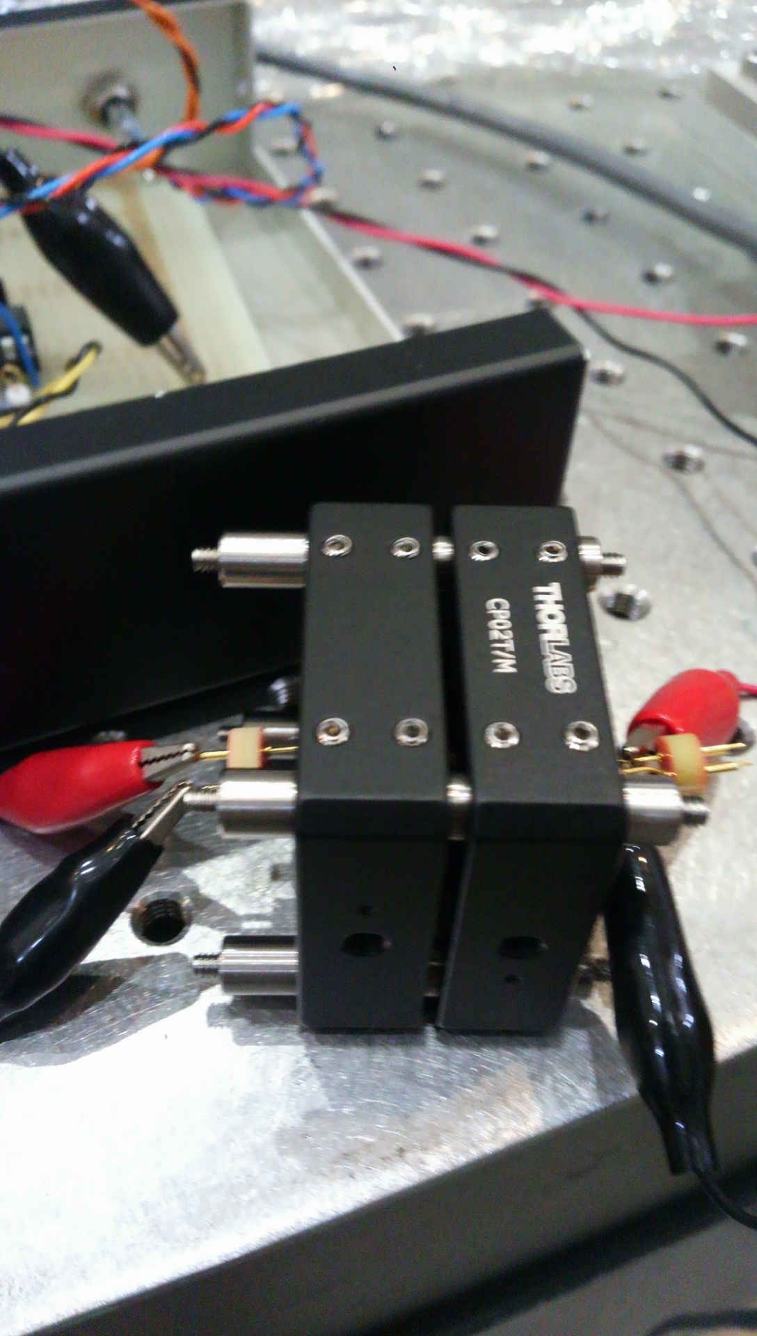
It is a quite simple setup holding a LED and PD closely with Thorlabs jigs (see pic).
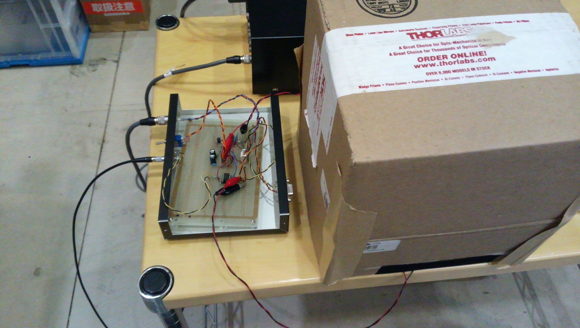
For the driver for the LED and PD, today I just use the Okutomi-kun's circuit (made based on the actual OSEM satellite box design, but a little bit modified).
- PD: Hamamatsu S1223-01
- LED: OP232 (I'd like to change this to TSTS7100...)
When the LED is turned on, the DC ouput of the PD driver is 1.5 V; the transimpedance is 38.3k Ohm, so the photocurrent would be about 40uA. According to the specification sheet, the PD would have about 0.55 A/W at the wavelenth (OP232's light is 890nm), so the corresponding light flux collected by the PD would be around 72uW. Probably the current supply to the LED became too narrow in the Okutomi-kun's circuit (which was Akutsu's direction, sorry). The power supply of the driver is +/-14V, so even if the LED become brighter, the PD can deal with it.
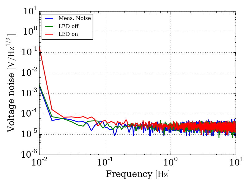
Anyway, firstly I just setup the FFT analyzer (Agilent 35670A) so that it has DC coupling (the "range" was around 1.5V), but the dynamic range of the measurement system gets ruined due to the large DC voltage described above (see the graph attached).
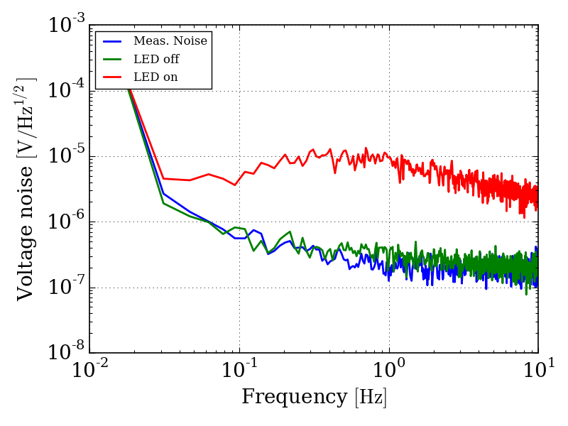
Then today I simply set AC coupling and then the "range" can be reduced to around 12mV, and the measurements appear to be meaningful so far. As I'm not sure well what will happen in the lower frequency range when you select the AC coupling mode, so it would be better to use SR560 to cut DC signal because we can measure the transfer function and can be calbirated afterwards.
[Abstract]
For measuring the LED intensity noise, the large DC voltage spoils the dynamic range of the FFT analyzer. The AC coupling could be usable to overcome the situation, so the difference between the AC and DC coupling inputs of 35670A's are measured. We should include the fit function for the calibration of measured data with the AC couping input.
[Measurements]
Measuring an input signal (or noise) with Ch1 and 2 of 35670A simultaneously and make it calculate the ratio Ch2/Ch1. A signal input is divided by a T-shape stuff and input into each channel.
- (a) Freq. response of Ch2/CH1 are measured with a random noise input created by the 35670A itself.
- (b) Swept sine mode to measure the same thing.
For the both cases, Ch2 is set to AC float and Ch1 to DC float. (I've tried other combination for just a confirmation.)
[Results]
The results of (a) and (b) are consistent, and the fit transfer function is approximated by
f(x) = (i*x/x0)/(1+i*x/x0)
and
x0 -> 0.485(5),
where I just assume f(x) -> 1 as x -> infinity.
You can use this function for the calbration when you use this 35670A with the AC coupling input (CH2).
Note: I'd like to avoid SR560s for the OSEM screening setup, as it appears to have large noise comparing to what I want to measure in the low frequency region, and each SR560 looks to have different noise level one by one... maybe our SR560s are getting old since they had been bought in 1998; one of them even sometimes has a jump in the DC offset during the measurement.