Participant: Matteo and Yuhang
Since we can do the calibration from time to frequency, I did some characterization work about OPO.
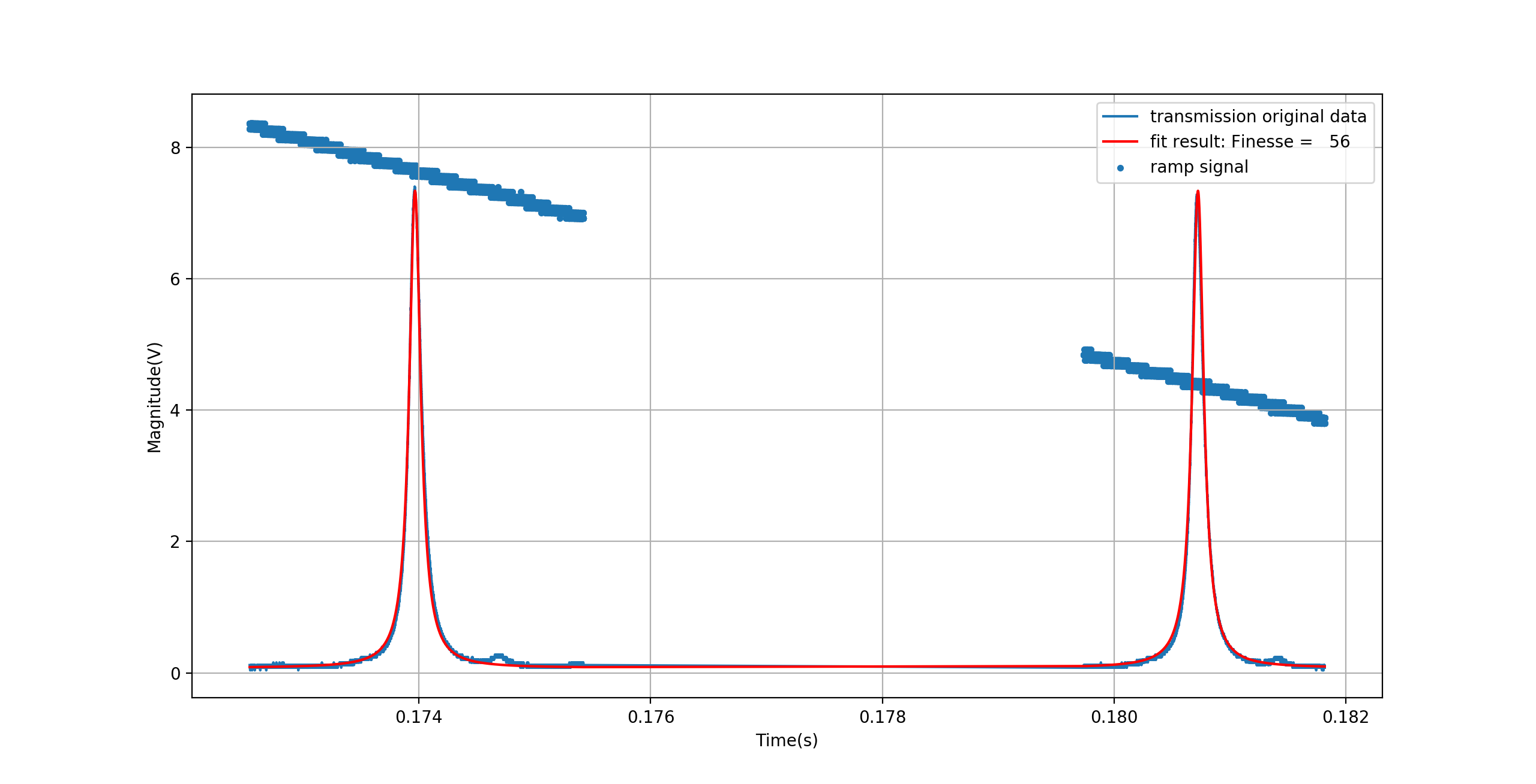
0. Fit Finesse of OPO
All the other measurement needs the value of the finesee, because there is coupling between some parameters of airy function(FSR and the finesse). So we use the measuremt which has two TEM00. It has a clear FSR, so that it can degenerate and give a better fit of the finesse. Then we use this fit value as an initial value reference for the finesse of other fits. Besides, here we take only the data around TEM00 to avoid the influence of higher order modes to the fit.
Result is finesse = 56 +/- 0.04. Detail is shown in attached figure 1.
Note: We found the high voltage driver now behaves very well. Since all the data we took for ramp comes from the monitor chanel of high voltage driver, so we think we can trust it. The good thing is that the ramp signal is quite linear and without distortion. So we think it should be fine to just take it as the real drive we send to the piezo of OPO.
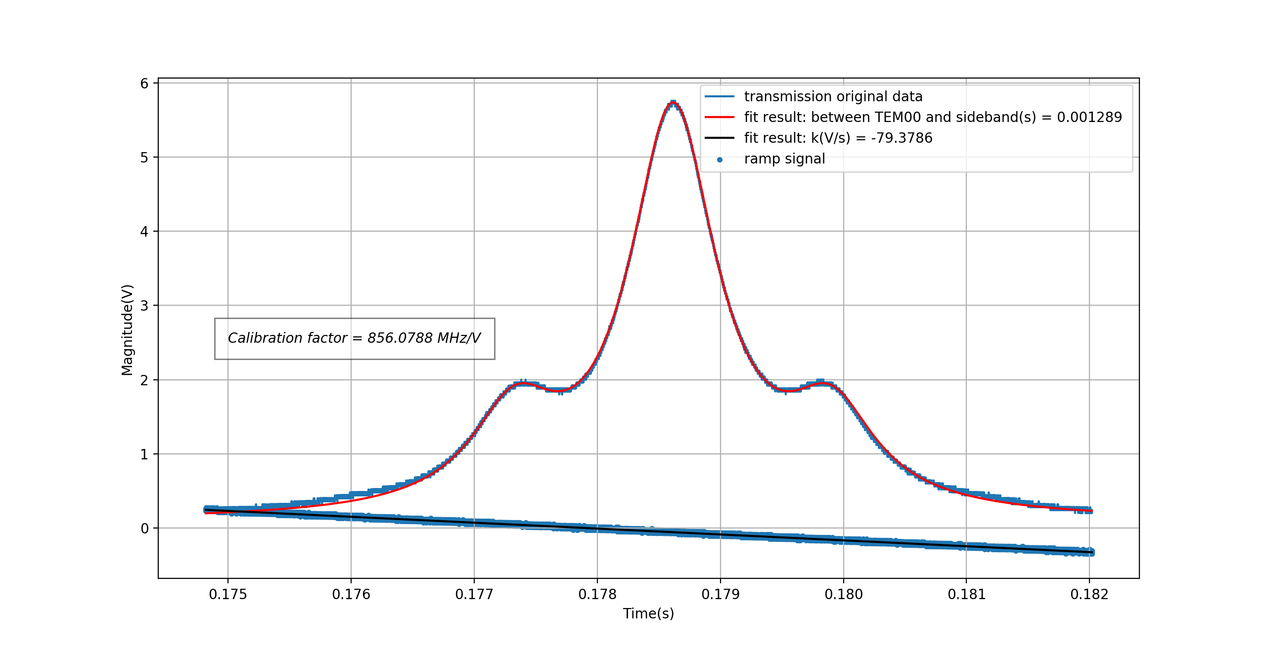
1. Find calibration factor
The method is to use airy function to fit TEM00 and sidebands. The purpose is to find the time distance between TEM00 and one of the sidebands. Then we can convert this time distance to voltage distance by using the ramp signal. This voltage distance corresponds to 87.6MHz(the resonant frequency of EOM). This new resonant frequency is because of the repair of EOM. After the repair the resonant frequency becomes from 88.1245MHz to 87.6MHz. The calibration factor of frequency/voltage is universal and can be used to all the measurement of our OPO.
See attached figure 2. The result is cal = 856.08 +/- 0.19 MHz/V.
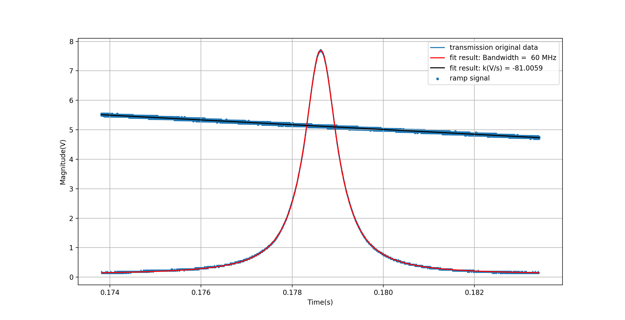
2. Fit of bandwidth
Since we have the calibration factor. We used the only TEM00 peak did the fit of bandwidth. In the code I attached, you can find every time I calculate the slope of ramp. It is quite cumbersome, but it is not avoidable. It is crucial to have a precise result. The result is shown in attached figure 3. BW = 59.93 +/- 0.21.
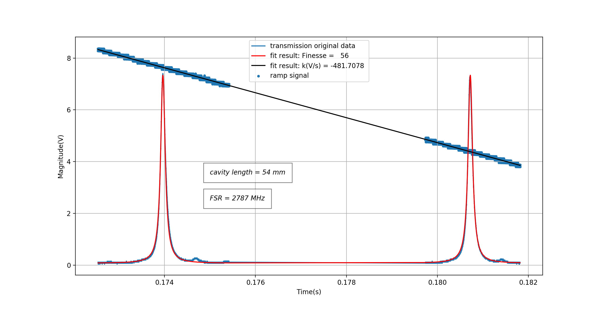
3. Fit of FSR and estimate of cavity length
We use again the data with two TEM00 fit the FSR(FSR is 2785.3 +/- 0.7 MHz) and cavity length(L = 53.855 +/- 0.013 mm). The method is similar with the fit of bandwidth. According to the result of FSR, we found the estimate of cavity length is 54mm. This is quite strange since according to the assemble picture Matteo uploaded and his Phd thesis, it should be around 35mm. Our result is 20mm longer than this nominal value. I guess there maybe something wrong. I will try to figure it out.
Finally, I also upload the code I used as a pdf file.