NAOJ GW Elog Logbook 3.2

Objective: [In continuation to elog 3145]
1. Testing the new RF switch HSWA4-63DR+
Details:
1. The new RF switch has 4 RF terminals (which can behave as both input and output) and 3 control terminals. The RF common port can behave as output or input depending on how we treat the RF terminals.
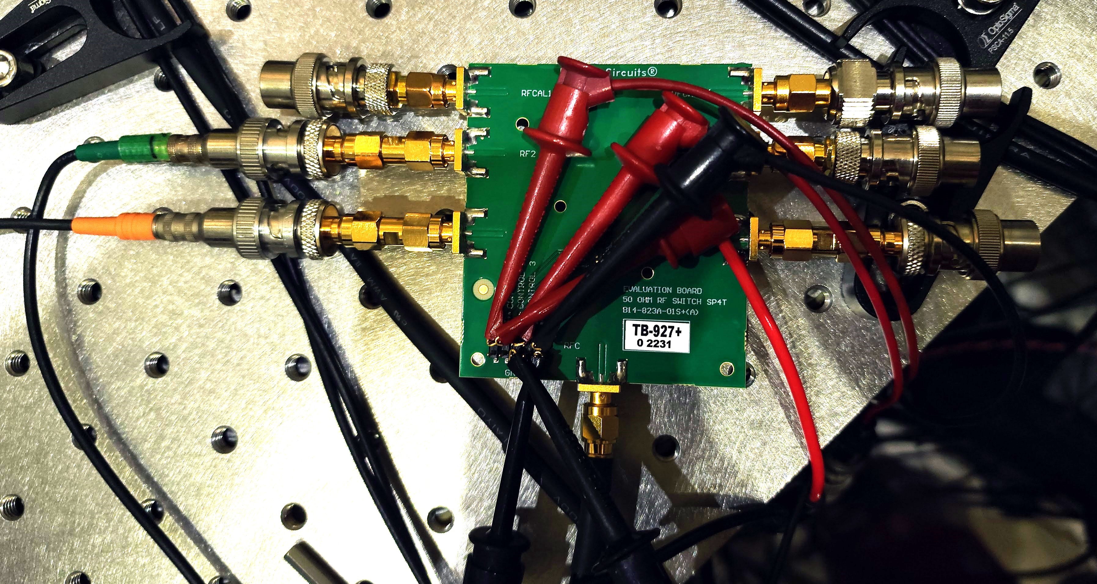
2. The RF switch was supplied a voltage (using voltage supply) and control voltage to two control terminals (using DC offset from function generator). The RF common port was treated as input and was connected to the output of the RF driver. The output of switch was collected at RF1. All the other ports were terminated using a 50 Ohm terminator. I also made sure that it didn't touch the table top as RF switches are sensitive to electrostatic discharge and commonly this disrupts the output. The output of the RF switch was seen at the RF1 port, in the oscilloscope. See Fig 1 for RF switch setup.
The input was provided as mentioned in the table
| Terminal | Values Applied | Specifications from Datasheet |
| VDD | 4 V | 2.3 V to 5.5 V |
| Control Voltage | -0.3 V to 3.6 V | |
| Control Voltage Low | 0 V | -0.3 V to 0.6 V |
| Control Voltage High | 2 V | 1.17 V to 3.6 V |
3. The control terminal behaves as a TTL(Transistor-Transistor logic) and can switch on or the output depending on their state. The logic of the control for RF1 is as follows:
| Control 1 | Control 2 | |
| RF1 ON | High | Low |
| RF 1 OFF | Low | Low |
Although there are 3 controls for this switch, we can leave control 3 unconnected.
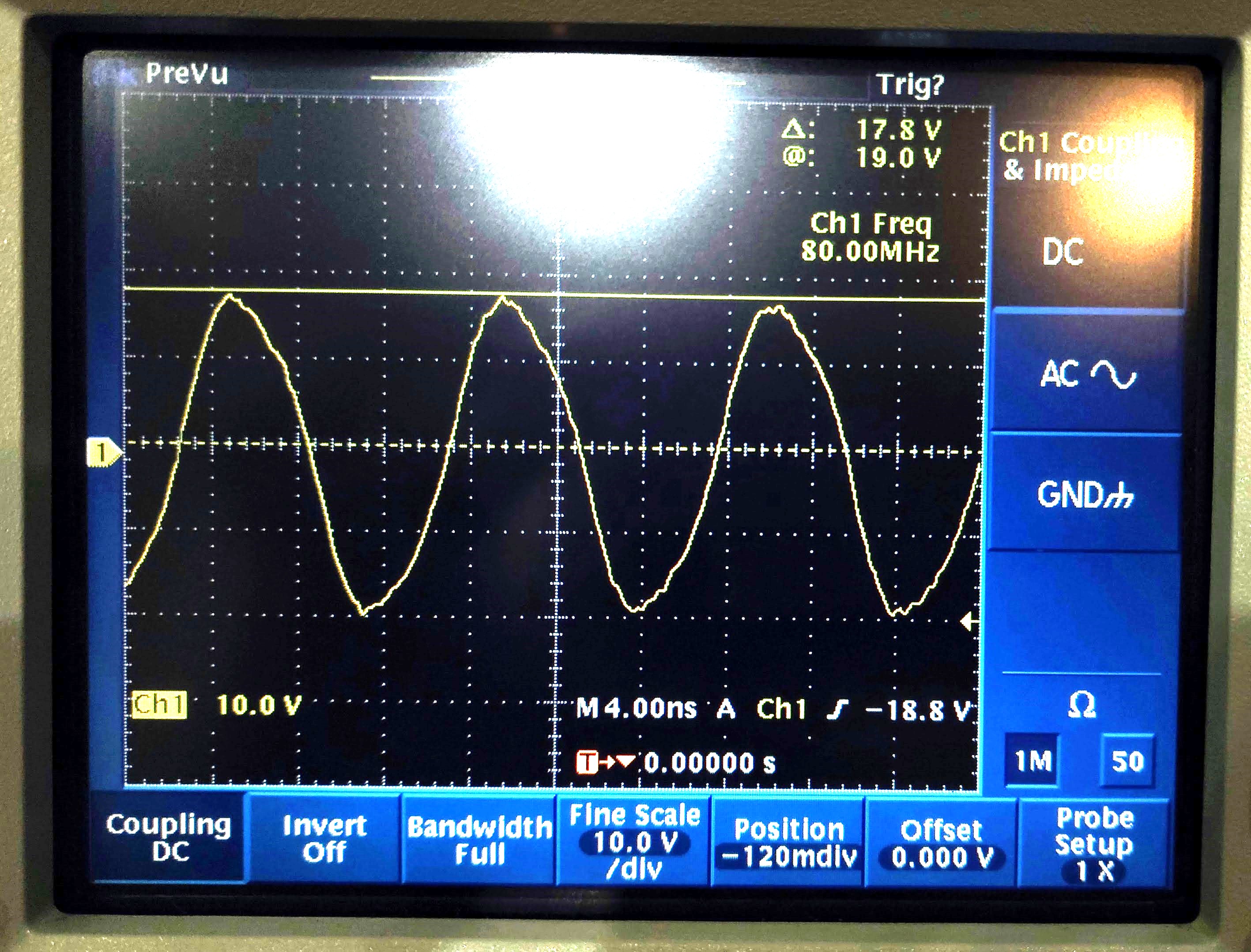
4. RF driver : First I checked the output of RF driver. The RF driver is given a 9.71 V tuning voltage (to make 80Mhz for the AOM) and 1 V input. The output of 80 Mhz frequency is as seen in Fig 2. (When I made the setting of oscilloscope to 50 Ohm impedance, I couldn't change the scale of channel beyond 1 V and so couldn't see the signal in the frame. When I tried the autoset setting, it made the impedance to 1MOhm. This is the only oscilloscope I had which had 50Ohm option but uses a floppy disk and so I had to use the 1MOhm impedance option)
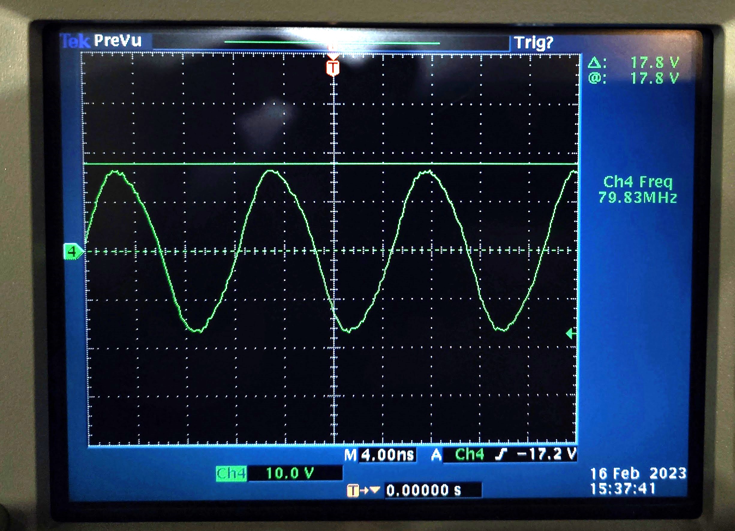
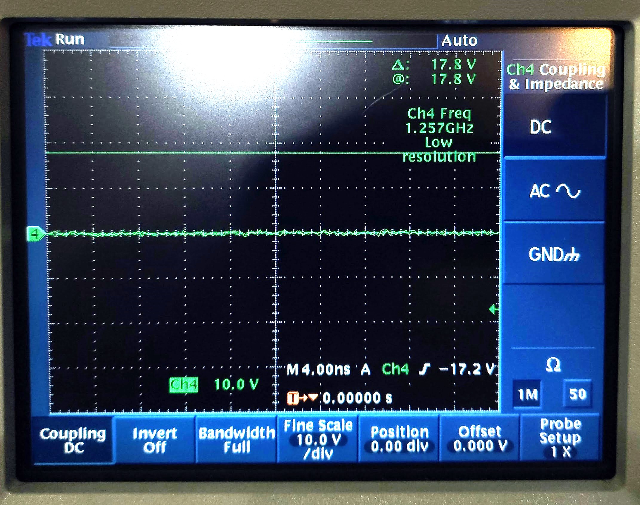
5. RF switch : The output of RF switch is as expected, and is the same as the RF driver output. See Fig 3 for the ON state and Fig 4 for the OFF state.
Next Step:
1. Connect the output of the switch to AOM
2. Lock the cavity and measure the ringdown appropriately.
Items Borrowed: I took 3 cables and a 50Ohm terminator required for this setup from elec shop. I have returned the multimeter that I borrowed previously to elec shop. I apologize for any inconvenience I may have caused.