NAOJ GW Elog Logbook 3.2

After closing the control loops of pitch and yaw of the telescope mirror in the PR tank, I tried to calibrated the signal in order to have an estimation of the angular motion of the mirror.
The displacement of the beam on the PSD given to a rotation in yaw on of an angle delta is given by
x = 2* arm* delta
Where arm is the distance between the mirror and the PSD.
A dispacement of the beam on the PSD of an amount x corresponds to a PSD voltage output of x/cal.
So delta = Vout*cal /(2*arm)
I measured the calibration factor of the PSD for 4 different powers in order to check if the normalized calibration (that is the calibration divided by the PSD voltage sum) was constant.
I found
| V_sum | Normalized calibration |
| 6.94 V | 0.0071 m |
| 11.5 V | 0.0068 m |
| 13.6 V | 0.0073 m |
| 14.4 V | 0.0071 m |
mean (n_cal) = 0.0071 std (n_cal) = 0.0002 In order to recover the appropriate calibration (m/V) this value should be dived by the V_sum measured each time.
Assuming arm = 1.20 m +/- 0.15 m (the precison on this measurement can be increased by measuring the optical lever arm next time we open PR tank)
and having measured V_sum = 13.3 V
we have
Cal_tot = n_cal/(2*arm*V_sum) = (2.2 +/- 0.3 ) e-4 [1/V] (percentage error 13% to be improved by better measuring the arm)
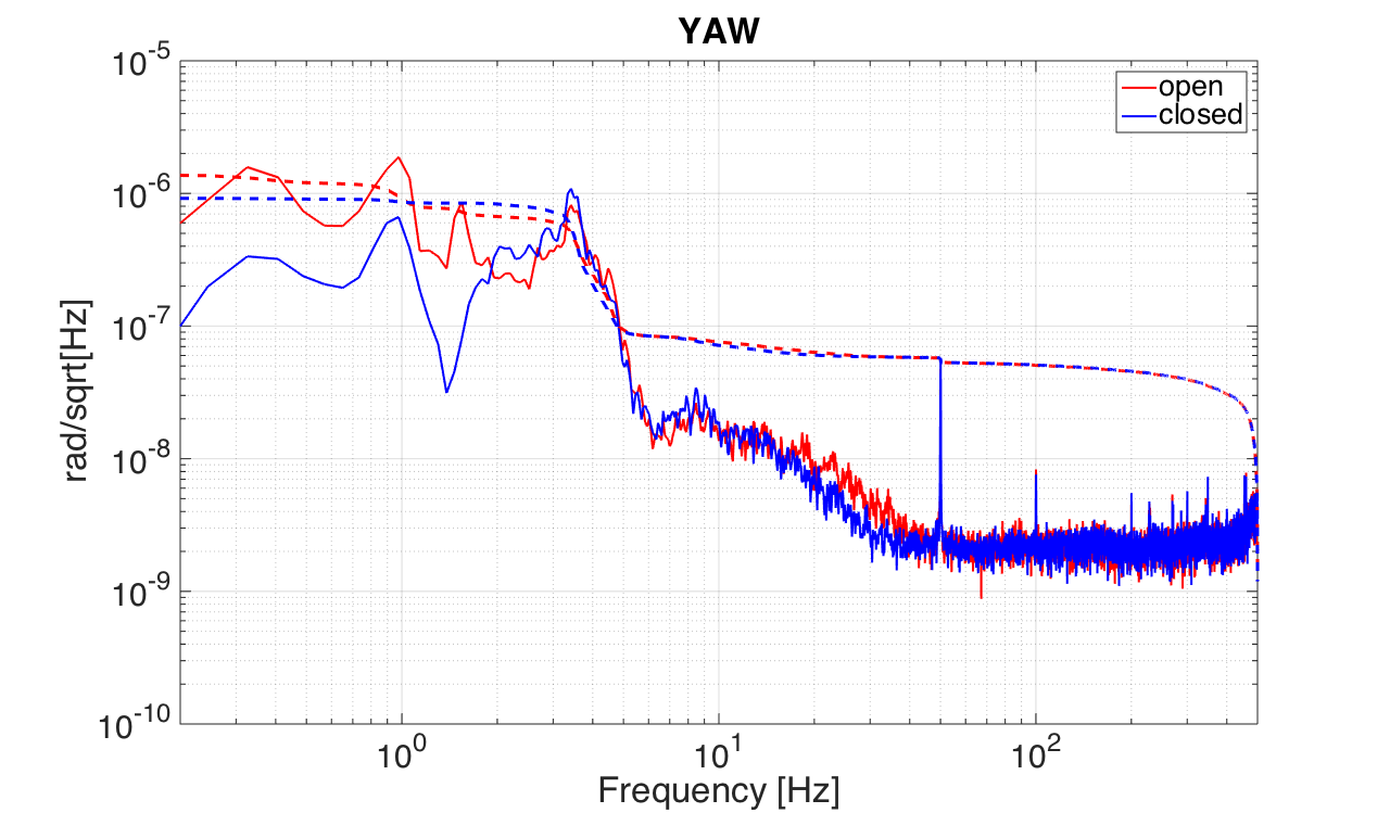
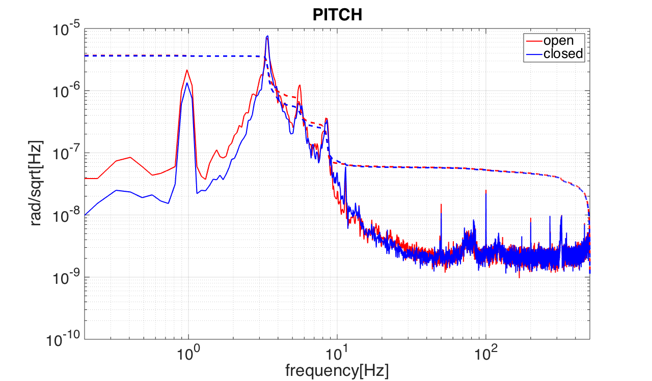
The comparison between the calibrated spectra with open and closed loops for pitch and yaw is shown in figures 1 and 2.
Some remarks:
1)In both cases the RMS seems to be dominate by the displacement in the region between 3-10 Hz.
2) Since the optical lever makes use of two steering mirrors directly fixed on the stack (see entry 262), this could not be a real motion of the mirror but a motion of the stack
3) This shoud be understood in order to improove the filter shape (Shoud we gain in that region or not?)
NB. For the pitch calibration we need to take into account an additional factor, equal to the the cosine of the incidence angle of the beam on the mirror (see 3rd attache picture)
y = 2* arm* delta* cos(alpha)
THIS FACTOR HAS NOT BEEN TAKEN INTO ACCOUNT IN THE PITCH PLOT WHICH SHOULD HAVE BEEN MULTIPLIED BY A FACTOR 1.412 (since alpha is 45°)